Super Famicom / SNES File Formats
Edit on Github | Updated: 2nd April 2026Super Famicom / SNES File Formats
This page is a practical reference for common SNES file formats used for developing games, including source code files (.ASM), audio files and artwork assets such as palettes, tiles, screen layout, object layout, and CAD-side metadata.
Source and Build Files
The table below lists the relevant entries.
| Extension | What it is |
|---|---|
| ASM | 65c816 assembly source |
| DEF | shared definitions and symbol layouts |
| REL | relocatable object or linked module |
| CNF | tool configuration blobs (often project/workspace settings consumed by SFDB and wrapper scripts) |
| MAKE / makefile | build recipes |
| BAT | DOS helper scripts used by tools and pipelines |
Glossary of Key Terms
If you are new to SNES-era workstation and build tooling, this quick glossary should help:
- SFDB - A Super Famicom development-time tool used in build and debug workflows. It is typically launched as sfdb -9
and expects a project configuration stored in a binary `*.cnf` file. - SFDB program file - A plain-text manifest used by sfdb-adjacent tooling to list binary assets alongside the ROM addresses and sizes they should occupy. The
tarakautility converts the manifest into a.mapreport, andazraelcan then merge and validate multiple.mapfiles for overlaps and bank overflow.
2D Artwork Files
The artwork files are all intended to be used by an internal Nintendo tool called S-CG-CAD or SCAD on a Sony NEWS workstation and the formats are designed to stack together:
| Layer | Purpose | Usually paired with |
|---|---|---|
| COL | palette rows (colors) | CGX, SCR, OBJ |
| CGX | tile graphics banks | COL, SCR, OBJ |
| SCR | background tile placement and attributes | CGX, COL |
| OBJ / OBX | sprite and object placement, text-as-objects | CGX, COL |
| SFX | CAD-side screen metadata | SCR, OBJ, CGX, COL |
These file types come from a Sony NEWS workstation art pipeline tool commonly referred to as S-CG-CAD or S-CAD. It was developed by long term Nintendo partner company SRD (Systems Research and Development).
In practice it behaves like an editor that saves multiple linked layers as separate files, rather than exporting one baked screen per save.
S-CG-CAD
The Computer Aided Design tool known as S-CG-CAD or S-CAD was developed by long term Nintendo partner company SRD (Systems Research and Development). It was intended to un on MIPS-based Sony NEWS workstations, the executables themselves are MIPS big-endian ECOFF (often reported as “MIPSEB ECOFF executable (paged)”).
If you have the ability to run these executables they can be found in the gigaleak in the NEWS.7z archive, specifically the NEWS_11 tape backup under the user hino’s home directory.
Executable Binaries
These are all executable files shipped alongside the SRD CAD tool bundle (both MIPS ECOFF binaries and wrapper scripts).
Utility binaries:
| Location | File | Type | Purpose |
|---|---|---|---|
srd/bin |
azrael |
ECOFF binary | MAP overlap and bank overflow checker that merges multiple MAPs into one report, marking issues per-line and returning non-zero status on errors. |
srd/bin |
taraka |
ECOFF binary | Converts an sfdb program file into a MAP file. |
srd/bin |
emln |
ECOFF binary | Symbol conversion helper used by the SRD pipeline (the binary identifies itself as emln - SFX). |
srd/bin |
lpf_xwdpr801ymc |
ECOFF binary | XWD-to-printer filter for the PC-PR801, intended to be used via lpr. |
srd/bin |
beep |
text/script | Rings the terminal bell. |
srd/bin |
chg |
csh script | Stream editor wrapper around sed that batch-edits files and keeps .BAK backups. |
srd/bin |
arc |
csh script | Backup and restore wrapper using tar plus compression (.Z). |
srd/bin |
sf |
csh script | Launches sfdb based on the single *.cnf in the current directory. |
srd/bin |
srd |
shell script | Prints a human-readable list of the registered SRD commands (and points at srd/doc/*.doc). |
srd/bin |
cad |
shell script | Setup hint script that reminds you to add /usr/local/srd/cad/bin and /usr/local/srd/cad/options to your PATH. |
srd/bin |
cad_chk |
csh script | Prevents starting a second CAD instance by checking running processes before calling cad. |
srd/bin |
obj_tool_chk |
csh script | Prevents starting a second OBJ tool instance by checking running processes before calling obj_tool. |
Main CAD application binaries:
| Location | File | Type | Purpose |
|---|---|---|---|
srd/cad/bin |
cad |
ECOFF binary | The main S-CG-CAD editor. |
srd/cad/bin |
cad_test |
ECOFF binary | Unstripped S-CG-CAD test build. |
srd/cad/bin |
pr_chr_B |
ECOFF binary | Printer output helper: character sheets (large). |
srd/cad/bin |
pr_chr_M |
ECOFF binary | Printer output helper: character sheets (medium). |
srd/cad/bin |
pr_chr_S |
ECOFF binary | Printer output helper: character sheets (small). |
srd/cad/bin |
pr_col_B |
ECOFF binary | Printer output helper: color palettes (large). |
srd/cad/bin |
pr_col_S |
ECOFF binary | Printer output helper: color palettes (small). |
srd/cad/bin |
pr_scr_B |
ECOFF binary | Printer output helper: screen output (large). |
srd/cad/bin |
pr_scr_S |
ECOFF binary | Printer output helper: screen output (small). |
srd/cad/bin |
pr_obj__ |
ECOFF binary | Printer output helper: OBJ layer. |
srd/cad/bin |
pr_obj_Q |
ECOFF binary | Printer output helper: OBJ sequence output. |
srd/cad/bin |
pr_pnl__ |
ECOFF binary | Printer output helper: panel output (PNL). |
srd/cad/bin |
pr_map__ |
ECOFF binary | Printer output helper: map output (MAP). |
srd/cad/bin |
tenso |
ECOFF binary | Hex/binary sender that talks to /dev/lp0 (printer port) and validates Intel HEX-like inputs. |
srd/cad/bin |
trans |
ECOFF binary | Another hex/binary sender with transmit_hex and transmit_bin routines, also targeting /dev/lp0. |
srd/cad/options |
obj_tool |
ECOFF binary | OBJ tool (“IWAWAKI SPECIAL Ver 2.00”) for sorting, control, editing, and image operations. |
srd/cad/options |
cad_clear |
ECOFF binary | CAD clear utility (references sfx_clear.hex). |
srd/cad/options |
sfx_main.OPT |
ECOFF binary | SFX option module (an executable plugin-style payload loaded from the CAD options area). |
srd/cad/environment |
mkcad_srd |
text/script | Creates a .CAD_SRD workspace directory and moves CAD state files into it. |
Reverse Engineering the executables
The main cad executable is unfortunately stripped (no debug symbols to get function names), but there is also an unstripped S-CG-CAD test build shipped as cad_test.
It is a MIPS big-endian ECOFF executable, and its ECOFF a.out optional header has vstamp = 0x020B, i.e. 2.11.
That vstamp is the “toolchain version stamp” written by the compiler/linker in MIPS ECOFF output, so this binary was built with a MIPS ECOFF toolchain stamping version 2.11 (the classic vendor cc/ld style toolchain used on NEWS-OS era MIPS systems), rather than something like modern GCC/ELF.
Unfortunately it is in ECOFF format which Ghidra has a hard time understanding, so the best thing to do is to convert it to an ELF like so (note that despite --strip-debug it will still have symbol names):
mipsel-linux-gnu-objcopy --strip-debug -O elf32-tradbigmips cad_test cad_test.elf
Now you can open in Ghidra and see over 2393 symbols! Of course many of these are static libraries that were compiled into the executable, the actual useful count is much lower.
Working Trees
A common convention is that the tool keeps a per-user working area in the home directory called .CAD_SRD.
That folder typically contains:
- tool state and options
- CAD working pages (often numbered sets of
SCR,CGX,COL, andOBJ) - the larger
OBXcompanion container in some setups - logs such as
CAD_ERR.TXT
That home-directory workspace is useful because it shows how the tool thinks about the data:
COLis a palette bankCGXis the tile bankSCRis the composed backgroundOBJ/OBXis the object layerSFXis per-screen metadata saved by the tool, not game runtime audio
Workstation to SNES Transfer Programs
The SNES graphics tools were set up to push work-in-progress data straight from a workstation to SNES development hardware.
In several leaked home directories, the CAD tool keeps a .CAD_SRD folder containing a small menu (CAD_pglist.dat) plus per-mode transfer lists (CAD.*.LST). Each .LST names a SNES-side helper program (an Intel HEX payload) and the files it expects to upload (typically CAD-0 through CAD-3 variants).
| Transfer program | What it was used for | Expected payloads (high level) |
|---|---|---|
| sfx_main | full screen preview transfer | CGX, OBJ, COL, SCR |
| tl_main1 | tile and palette focused preview | CGX, OBZ, COL |
| tl_main2 | full screen preview but with OBZ format and CAD.DAT | CGX, OBZ, COL, SCR, CAD.DAT |
sfx_main and tl_main2 both transfer enough data to show a full composed screen (.SCR), but they are aimed at different CAD workflows and they move different payload sets:
- sfx_main (the “full CAD screen” transfer) uploads CGX + OBJ + COL + SCR. It is the only one that explicitly expects the standard .OBJ object-layout files.
- tl_main2 (the “tile/layout” transfer) uploads CGX + OBZ + COL + SCR and also a CAD.DAT blob. It uses CAD.OBZ instead of per-slot .OBJ, and it has extra per-transfer state/config via CAD.DAT.
This is a useful lens for interpreting the formats on this page: the file types were designed to be transferred as a bundle, then interpreted by a small runtime on the SNES devkit.
COL Format - Color Palette
COL is a palette bank, so it stores the color data that can be used as a palette for tiles and sprite data.
It has 2 bytes per color and uses SNES BGR555 packed color in little-endian order, allowing 16 colors per palette row.
| Field | Value |
|---|---|
| Encoding | little-endian SNES BGR555 |
| Record region | 0x200 bytes (256 colors) |
| Common size | 0x400 bytes in S-CG-CAD saves (record region + tool metadata) |
| Colors | 256 color words |
| Layout | 16 palette rows of 16 colors |
| Row slot 0 | commonly treated as transparent or backdrop-like |
Byte Layout
COL is a flat array of 16-bit color words.
| Offset | Size | Meaning |
|---|---|---|
0x0000 |
2 |
color 0, palette row 0 |
0x0002 |
2 |
color 1, palette row 0 |
| … | … | … |
0x001E |
2 |
color 15, palette row 0 |
0x0020 |
2 |
color 0, palette row 1 |
| … | … | … |
Each 16-bit word is packed as:
| Bits | Meaning |
|---|---|
0-4 |
red |
5-9 |
green |
10-14 |
blue |
15 |
unused (0) |
Decode rules:
- read a little-endian 16-bit value
v r5 = (v >> 0) & 0x1F,g5 = (v >> 5) & 0x1F,b5 = (v >> 10) & 0x1F- expand 5-bit to 8-bit with
(c5 << 3) | (c5 >> 2)
Tool metadata (S-CG-CAD)
S-CG-CAD saves often append tool metadata after the 0x200-byte record region, making a common on-disk size of 0x400 bytes:
| Offset | Size | Meaning | Notes |
|---|---|---|---|
0x0200 |
0x100 |
tool header block | Observed to begin with ASCII NAK1989 S-CG-CADVer... in multiple assets. |
0x0300 |
0x100 |
per-row tool metadata | S-CG-CAD writes 0x80 bytes of row data (32 rows x 4 bytes) and leaves the remaining bytes as reserved/zero. |
In the S-CG-CAD toolchain, only a small part of this metadata is clearly used in normal open/save flows. If you are writing a rewriter, preserve 0x0200..0x03FF exactly where possible.
The per-row metadata is written as a flat table at 0x0300..0x037F:
- 32 entries (one per palette row), 4 bytes per entry.
- Each entry is copied from the low byte of four 32-bit words in a 16-byte-per-row structure (bytes at offsets
+3,+7,+0x0B,+0x0Ffrom a0x10-byte stride per row). - These bytes appear to be S-CG-CAD editor-side palette table state (preview colors / attribute selectors) rather than SNES runtime palette data. The tool updates them via the palette table UI and uses
cgbankto decide which bits are meaningful when rendering the palette table.
Important note: S-CG-CAD does not appear to use the 0x0200..0x03FF metadata when opening a normal .COL through its usual file open path. The metadata is still saved and is useful for round-tripping, but the separate “restore from backup” path uses a different stream shape: 0x200 bytes of color words, followed by 0x200 bytes of palette metadata, followed by a single byte of cgbank.
What cgbank does (S-CG-CAD)
The cgbank setting is the CAD-side tile bank selector used when interpreting and exporting CGX data.
Although the name is misleading, cgbank in this tool acts like a per-palette “color mode” selector that affects how the editor maps palette indices into its workstation-side 8-bit color table.
The tool’s palette update routine shows three main behaviors based on cgbank:
cgbank = 0- updates a 32-entry repeating window (index & 0x1F)cgbank = 1- updates a 128-entry repeating window (index & 0x7F)cgbank = 2- updates all 256 entries (with special-cased reserved indices likefore,back, andmixc)
This is editor/UI behavior, not SNES runtime palette data, but the chosen mode is still persisted in S-CG-CAD’s save/backup flows.
Interactive COL Viewer
This viewer loads a COL file and shows every row as swatches.
CGX Format - Color Graphics (Tile Data)
CGX is a raw tile graphics bank, stored from byte 0. Although the extension is CGX, it was also used for original Game Boy assets despite only being shades of grey or green.
| Field | Value |
|---|---|
| Tile shape | 8x8 pixels |
| Bit depth | commonly 4bpp, sometimes 2bpp or 8bpp |
| Interpretation | planar SNES tile bitplanes |
Common sizes are consistent with raw 8x8 tiles:
| Size | 4bpp tiles | Notes |
|---|---|---|
| 17,664 bytes | 552 | compact text or small UI banks |
| 34,048 bytes | 1,064 | common menu and title banks |
| 65,792 bytes | 2,056 | large shared banks |
S-CG-CAD also uses fixed “standard bank” CGX containers that bundle 1024 tiles plus tool metadata. These are easiest to recognize by file size:
| File size | Record region | Bit depth | Tiles | Tail bytes | Notes |
|---|---|---|---|---|---|
0x4500 |
0x4000 |
2bpp | 1024 | 0x100 header + 0x400 per-tile table |
S-CG-CAD reads 2bpp planes and ORs tile_table[i] << 2 into each pixel index. |
0x8500 |
0x8000 |
4bpp | 1024 | 0x100 header + 0x400 per-tile table |
S-CG-CAD reads SNES 4bpp planes and ORs tile_table[i] << 4 into each pixel index. |
0x10100 |
0x10000 |
8bpp | 1024 | 0x100 header |
S-CG-CAD reads SNES 8bpp planes; no per-tile table is stored in this variant. |
In these S-CG-CAD variants the first record region bytes are still standard planar tile data and can be decoded normally. The extra 0x100 header commonly begins with ASCII NAK1989 S-CG-CADVer..., and the per-tile table is tool-specific metadata that affects how the editor constructs 8-bit pixel indices.
Per-tile table (S-CG-CAD)
In the 0x4500 and 0x8500 variants, S-CG-CAD stores a 1024-byte table after the 0x100 header. Each entry is one byte per tile. The tool uses it as a per-tile “pixel index prefix”:
- For 2bpp CGX (
0x4500), S-CG-CAD combines it aspixel_index = (tile_table[tile] << 2) | pixel_2bpp. - For 4bpp CGX (
0x8500), S-CG-CAD combines it aspixel_index = (tile_table[tile] << 4) | pixel_4bpp.
That means the table acts like a per-tile palette selector in editor space (it chooses which group of 4 or 16 colors the tile’s pixels index into), even though the underlying record region is still standard planar 2bpp/4bpp tile data.
In the 2bpp variant there is an extra twist: the tool packs a bank-wide setting into the top bits of each per-tile table byte. After the tool’s decode step, the effective 8-bit editor pixel index behaves like:
pixel_index = (header_0x23 << 5) | ((chars[tile] >> 2 & 7) << 2) | pixel_2bpp
In other words, part of the “prefix” is per-tile and part is effectively a per-bank constant in the CAD preview pipeline.
Some bytes inside the 0x100 CGX header are set by the tool and appear to mirror editor state:
| Offset | Size | Meaning | Notes |
|---|---|---|---|
0x20 |
1 |
cgbank mode |
Same mode described in the COL section; affects how pixel indices are interpreted in the editor. |
0x21 |
1 |
colormap bank index | A small selector (0-3) that affects the CAD tool’s workstation-side preview colormap. |
0x22 |
1 |
BG/OBJ palette toggle | A 1-bit toggle that affects how the CAD tool configures its preview colormap. |
0x23 |
1 |
cell index (2-bit) | A small selector (0-3) that affects CAD preview paths. In the 2bpp standard-bank variant it also feeds the bank-wide prefix contribution described above. |
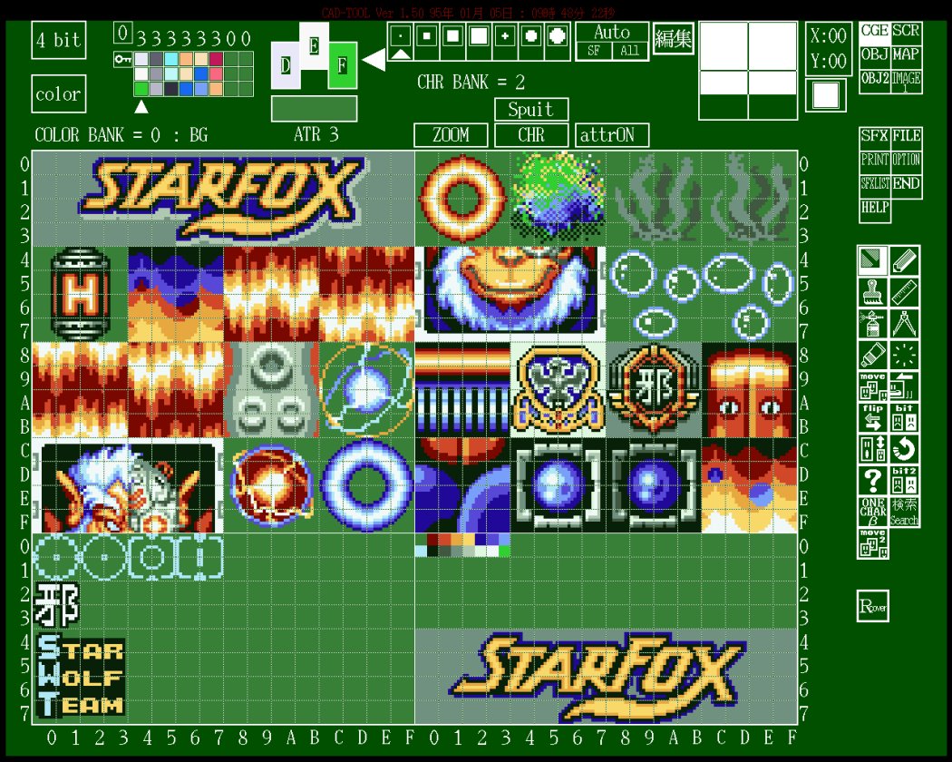
The Nintendo CGE UI (Color Graphics Editor) explicitly shows 4bit and 8x8 editing for this data family.
This viewer renders CGX as tiles, and optionally applies a COL palette.
Byte Layout (SNES Planar Tiles)
CGX is a packed stream of 8x8 tiles with no header. Tile N starts at N * bytes_per_tile.
| Bit depth | Bytes per tile | Per-row layout |
|---|---|---|
| 2bpp | 16 |
2 bytes per row, 8 rows |
| 4bpp | 32 |
2 bytes per row for planes 0-1, then 2 bytes per row for planes 2-3 |
| 8bpp | 64 |
2 bytes per row for planes 0-1, then 2 bytes per row for planes 2-3, 4-5, 6-7 |
4bpp tile layout by offset:
| Offset | Size | Meaning |
|---|---|---|
0x00-0x0F |
16 |
bitplanes 0 and 1 for rows 0-7 (2 bytes per row) |
0x10-0x1F |
16 |
bitplanes 2 and 3 for rows 0-7 (2 bytes per row) |
For a given tile, row y and pixel x:
bit = 7 - x- plane bits come from the corresponding row bytes
- combine plane bits into a palette index (0-3, 0-15, or 0-255 depending on bpp)
SCR Format
SCR is a background screen composition container.
The common SCR layout is fixed-size:
| Range | Size | Meaning |
|---|---|---|
| 0x0000 to 0x1FFF | 2,048 bytes | block 0, 32x32 tilemap words |
| 0x2000 to 0x3FFF | 2,048 bytes | block 1, 32x32 tilemap words |
| 0x4000 to 0x5FFF | 2,048 bytes | block 2, 32x32 tilemap words |
| 0x6000 to 0x7FFF | 2,048 bytes | block 3, 32x32 tilemap words |
| 0x8000 to 0x80FF | 256 bytes | metadata region (CAD signature often appears here) |
| 0x8100 to 0x82FF | 512 bytes | trailer region |
The main 16-bit words behave like SNES BG tilemap entries:
| Bits | Meaning |
|---|---|
| 0 to 9 | tile number |
| 10 to 12 | palette row |
| 13 | priority |
| 14 | horizontal flip |
| 15 | vertical flip |
Byte Layout
SCR is a fixed-size container with four packed 32x32 background tilemaps.
Each tilemap block is a 32x32 grid of 16-bit words:
- 32 x 32 = 1,024 entries
- 1,024 x 2 bytes = 2,048 bytes per block
Each entry is a 16-bit word with this bitfield layout:
| Bits | Meaning |
|---|---|
0-9 |
tile index (0-1023) |
10-12 |
palette row (0-7) |
13 |
priority |
14 |
horizontal flip |
15 |
vertical flip |
If you are writing a parser:
- read 16-bit
wfrom the file tile = w & 0x03FFpal = (w >> 10) & 0x07pri = (w >> 13) & 0x01hflip = (w >> 14) & 0x01vflip = (w >> 15) & 0x01
Endianness note:
- In a ROM or 65c816 runtime context, SNES tilemap words are typically stored little-endian.
- In the S-CG-CAD
save_scrpath, the tool explicitly byte-swaps each 16-bit word before writing it, andload_scrswaps it back after reading. That means S-CG-CAD-authored.SCRfiles are big-endian on disk for the 16-bit tilemap words.
S-CG-CAD also writes a 0x100 metadata header (starting with ASCII NAK1989 S-CG-CADVer...) at 0x8000, followed by a 0x200 trailer region. A few header bytes appear to mirror editor state:
| Offset (from 0x8000) | Size | Meaning | Notes |
|---|---|---|---|
0x40 |
1 |
scbank bit depth mode |
Selects how the screen tool interprets tile graphics and pixel indices in its internal preview buffer. In the traced paths: 0 behaves like 2bpp (pixel indices 0-3 plus a per-tile 3-bit prefix), 1 behaves like 4bpp (pixel indices 0-15 plus a per-tile 3-bit prefix), and 2 behaves like 8bpp (raw 0-255 pixel indices). |
0x41 |
1 |
unknown SCR mode byte (2-bit) | A small per-screen mode field used by the CAD tool. The exact meaning has not been traced yet, but the value is preserved on load/save. |
0x42 |
1 |
screen tile size mode | Controls how the CAD tool composes tiles for preview and stamping. In the traced behavior, 0 acts like 8x8 and 2 acts like 16x16 (composed from 4 tiles: tile, tile+1, tile+0x10, tile+0x11). |
0x43 |
1 |
referenced CGX bank (2-bit) | Which of the CAD tool’s CGX banks this screen uses when previewing tiles (0-3). |
0x44 |
1 |
screen colormap bank index | A small selector used by the CAD tool’s preview colormap (0-3). |
0x45 |
1 |
screen color selector byte | Additional CAD preview color selector byte (interpretation depends on scbank). |
0x46 |
1 |
screen color selector byte | Additional CAD preview color selector byte (interpretation depends on scbank). |
0x47..0x48 |
2 |
stamp base tile index (16-bit) | Base tile index used by the CAD tool when stamping tiles into the screen, and displayed in the UI as a 3-nibble hex value like ABC. |
Trailer region note:
- In
save_scr, the trailing0x200bytes are written as0xFFfill. - In
load_scr, the tool reads the0x200bytes (four0x80chunks) but does not appear to interpret them in the traced code paths.
Toolchain conversion
Some pipelines include small conversion utilities that export a CAD-authored .SCR into a simpler table for PC-side tooling.
One example is stdscr.c (header: “NEWS-CAD (SCR_File) -> STD_SCR (*.STD)”, MS-DOS ver 1.11, 1992-04-13). It reads base.SCR as 4 blocks of 0x400 entries, but for each entry it takes one byte and discards the next byte, which effectively strips the upper byte of the 16-bit tilemap word (the byte that carries most attribute bits) and keeps the low byte.
It then repacks the four 32x32 blocks into a single 0x1000 byte output called base.STD:
- blocks 0 and 1 are placed side-by-side to form a 64x32 region (each 32-byte row becomes 64 bytes)
- blocks 2 and 3 are placed side-by-side to form another 64x32 region below it
In other words, this “MS-DOS screen” is not a DOS graphics format like a VGA framebuffer. It is a raw 4KB 64x64 grid of 8-bit tile indices, intended for quick viewing, printing, or importing into PC-side tools that do not need per-tile SNES attributes.
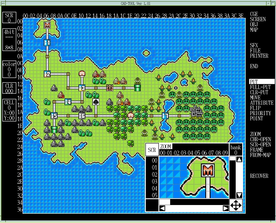
The CAD tool UI shows the same workflow split: screen, object, map, and SFX metadata as separate operations.
This viewer composes SCR using CGX and COL.
PNL Format
PNL is the CAD-side “panel” format: a large tile selection surface used as the source for MAP stamping and MAP-to-SCR conversion.
In the S-CG-CAD toolchain, PNL is stored as a fixed-size container.
In the NEWS archives, *.PNL files are consistently 0x10100 bytes (65,792 bytes).
| Range | Size | Meaning |
|---|---|---|
0x0000 to 0x00FF |
0x100 |
header (CAD provenance + editor state) |
0x0100 to 0x80FF |
0x8000 |
tile table (16-bit words, big-endian) |
0x8100 to 0x100FF |
0x8000 |
per-tile flag table (16-bit words, big-endian) |
This viewer can derive a screen tilemap directly from a *.MAP + *.PNL pair so you can validate flip, priority, and palette propagation without exporting a *.SCR from the original tool.
Header fields (S-CG-CAD)
The first 0x20 bytes are typically an ASCII CAD provenance string like NAK1989 S-CG-CADVer....
The S-CG-CAD load/save path consumes a small set of header bytes as per-bank editor settings. Not every field is fully understood yet, but the offsets and bit masking are stable:
| Offset | Size | Meaning | Notes |
|---|---|---|---|
0x0060 |
1 |
colormap mode | Stored as plbank per panel bank. This controls which colormap upload path is used (for example 32-color uploads vs 128-color uploads vs full 256-color uploads). |
0x0061 |
1 |
Mode 7 enable flag | A 0/1 flag used to toggle the Mode 7 label in the UI for the currently selected bank. |
0x0062 |
1 |
panel graphics mode | A small mode selector used to choose panel and map conversion routines. In traced code paths, only bit 1 is consumed (header[0x62] & 0x02), so the stored value behaves like 0 or 2. |
0x0063 |
1 |
referenced CGX bank | header[0x63] & 0x03. This is the bank used when sampling tile graphics in some panel operations. |
0x0064 |
1 |
panel colormap bank index | header[0x64] & 0x03. This is the “color bank” selector used by the panel preview colormap UI. |
0x0065 |
1 |
colormap selector A | A per-bank selector used when choosing which slice of the internal preview colormap tables to upload. |
0x0066 |
1 |
colormap selector B | A secondary selector used only in some colormap modes (see below). |
0x0067..0x0068 |
2 |
base tile index | A 16-bit value set from the character window selection. In traced UI code it is displayed as a 3-nibble hex value as a reminder of the last “character tile” you picked, and it is preserved in the PNL header across saves. |
0x0069 |
1 |
panel tile width exponent | Used as 1 << (header[0x69] & 0x1F) in panel and map conversion logic. |
0x006A |
1 |
panel tile height exponent | Used as 1 << (header[0x6A] & 0x1F) in panel and map conversion logic. |
Other header bytes in the 0x60..0x6A range are preserved and appear in the S-CG-CAD save path, but their exact UI meaning has not been traced yet.
How the header drives panel preview colors
The tool uses the header bytes above to decide how to upload and index colors for the panel preview:
colormap modeselects the upload mode (a small fixed palette vs a larger subset vs a full 256-color ramp).- the
panel colormap bank indexand the twocolormap selectorbytes choose which slice of the internal colormap tables is sent to X11 for preview.
In other words, PNL does not embed actual SNES palette data. It stores the panel editor’s “how to interpret pixel indices and which colormap slice to show” state.
The two selector bytes are not always used in the same way:
- In the 32-color upload mode, the tool uses both selector A and selector B to pick a 32-color slice.
- In the 128-color upload mode, only selector A is used (selector B is effectively ignored).
- In the 256-color upload mode, neither selector is used (the upload is controlled by the bank index byte instead).
How the width and height exponents are used
The panel tile width exponent and panel tile height exponent do not change the on-disk table size.
They change how the tool treats a single panel tile selection when converting between panel, map, and screen:
metaWidth = 1 << (header[0x69] & 0x1F)metaHeight = 1 << (header[0x6A] & 0x1F)
When these values are greater than 1, one “logical tile” selection is treated as a block of multiple 8x8 tiles. This is how the editor supports workflows like 16x16 stamping and map conversion based on larger metatiles without changing the underlying 8x8 tile storage.
Tile table word layout
The tile table is 0x4000 16-bit words.
Each word encodes the tile id plus a few per-tile attributes used by S-CG-CAD’s panel editor.
| Bits | Mask | Meaning |
|---|---|---|
| 15 | 0x8000 |
vertical flip |
| 14 | 0x4000 |
horizontal flip |
| 13 | 0x2000 |
priority |
| bits 12 to 10 | 0x1C00 |
palette row (0-7) |
| bits 9 to 0 | 0x03FF |
tile id (0-1023) |
The S-CG-CAD decomp stores these into an internal 6-byte per-tile entry used throughout the panel and map code:
vflip = (word >> 15) & 0x01hflip = (word >> 14) & 0x01priority = (word >> 13) & 0x01palRow = (word >> 10) & 0x07tileId = word & 0x03FF
These bit meanings line up with how the tool’s panel flip actions work:
- a horizontal flip toggles bit 14 (and swaps tiles left-to-right), and
- a vertical flip toggles bit 15 (and swaps tiles top-to-bottom).
That behavior confirms the two high bits are flip flags, not a CGX bank selector.
If you are round-tripping words, the S-CG-CAD load/save path treats the 16-bit word as big-endian on disk and does not byte-swap it in the PNL I/O functions.
What the priority bit means in practice
The priority bit is the same concept as the SNES BG tilemap “priority” flag (bit 13 in an on-console tilemap word).
It controls whether the tile is drawn in the high priority group for that background layer.
In S-CG-CAD workflows, this matters because:
- the panel editor lets you set priority per tile (for example with the panel priority tool), and
- when the tool converts panel or map data into SCR cell data, it copies the panel priority bit through so the resulting SCR tiles preserve the intended priority.
In traced MAP-to-SCR conversion, priority is taken from the panel tile entry whenever a MAP cell resolves to a panel tile. It is not gated by the MAP cell’s “attribute source” flag, which only affects how the final tile id is chosen.
Per-tile flag table
The second table is also 0x4000 16-bit words.
In the traced S-CG-CAD load path, only bit 15 is consumed and stored as a 1-byte per-tile flag:
flag = (word2 >> 15) & 0x01
This flag is used as the “tile present” / “tile active” check in multiple paths (for example, panel and MAP conversion logic treats tiles as empty when this flag is 0).
In real NEWS archive *.PNL files, the lower 15 bits of this second-table word are often non-zero.
S-CG-CAD does not appear to consume those bits in the traced code paths, so they are best treated as unknown/reserved metadata that other tool builds may use.
Common editor operations (what changes which bits)
The decomp shows that the panel editor treats the two big-endian tables as the authoritative state, and the UI tools mutate specific fields in-place:
- Erase / clear - clears the “present” flag for the selected region (this is what makes a tile slot empty).
- Palette row change - writes a new
palRowvalue (bits 12 to 10) for all present tiles in the selected region. - Priority change - writes a new
prioritybit (bit 13) for all present tiles in the selected region. - Flip - toggles
hflip(bit 14) and/orvflip(bit 15) for tiles in the selected region and swaps entries so the image stays visually consistent.
This is useful when reverse engineering real assets, because it tells you which fields are intended to be mass-edited as attributes rather than being treated as part of the tile id itself.
Attribute propagation into SCR
In the S-CG-CAD toolchain, PNL is the source of truth for per-tile attributes that eventually end up inside the SCR tilemap word. When a MAP cell resolves to a panel tile, the conversion copies these fields through:
| PNL field | SCR meaning |
|---|---|
vflip |
SCR vertical flip bit (bit 15) |
hflip |
SCR horizontal flip bit (bit 14) |
priority |
SCR priority bit (bit 13) |
palRow |
SCR palette row (bits 12 to 10) |
The tile id bits (SCR bits 0 to 9) are filled from either the panel tile id or from a default value depending on the MAP cell’s attribute source flag.
Panel dimensions and indexing
Although the file stores 0x4000 entries, many UI paths treat the panel as having a fixed row stride of 32 tiles.
This matches the MAP format, where panelX is 5 bits (0-31) and panelY is 9 bits (0-511), and the tool flattens the coordinates as:
panelTileIndex = panelY * 32 + panelX
So a practical mental model is “a 32x512 tile panel”, with scrolling and grouping handled in the editor.
Notes on the remaining unknown header bytes
The PNL header is 0x100 bytes, but the S-CG-CAD load/save path only consumes a small subset of offsets (0x60..0x6A and the provenance string).
If you are writing a parser, it is safest to treat the entire header as opaque and preserve it byte-for-byte on save. Even if a byte is not used by the code paths we traced, it may still matter for other tools, other CAD builds, or project-specific workflows.
OBJ and OBX Format
OBJ and OBX are framed object-layout containers used to place sprites and object-form text.
Container Layout
In the source archives there are at least two closely related “OBJ” layouts:
- the CAD toolchain layout used alongside
.OBX(6-byte slots) - a printer/report tool layout (
pr_obj__) that stores 10-byte entries and a larger frame range
| Format | Record region | Frame count | Slots per frame | Bytes per slot |
|---|---|---|---|---|
| OBJ | 12,288 bytes | 32 | 64 | 6 |
| Extended OBJ | 24,576 bytes | 64 | 64 | 6 |
| OBX (observed) | 49,152 bytes | 64 | 128 | 6 |
Files commonly append a CAD metadata tail after the record region.
Toolchain conversion
Some projects also include small conversion utilities that turn CAD-authored .OBX data into assembler-friendly tables for the game runtime.
One example is eobjcnvX.c, which reads a full 49,152-byte .OBX record region (64 * 128 * 6), filters to slots where the “display enable” flag (byte 0 bit 0x80) is set, applies a global X/Y offset, and writes the results out as eobj.dat using BYTE and HEX directives.
This is not a different on-disk .OBX format: it is a build-time export that (a) changes representation (text + directives rather than a binary container), and (b) intentionally alters some fields (it emits the packed word as two bytes and clears bits 0x30 in the high byte, which corresponds to dropping the priority bits in the packed attribute + tile word described below).
Entry Layout
CAD OBJ / OBX (6-byte slots)
Each slot is 6 bytes. In the S-CG-CAD toolchain, bytes 4..5 are treated as a single big-endian 16-bit value, not two independent bytes.
| Byte | Meaning |
|---|---|
| 1 | flags: bit 7 display enable, bit 0 size select |
| 2 | group info (tool classification) |
| 3 | Y displacement (signed 8-bit) |
| 4 | X displacement (signed 8-bit) |
| bytes 5 to 6 | packed attribute + tile word (big-endian, see below) |
Byte Layout
OBJ and OBX record regions are a flat array of 6-byte slots, grouped into frames.
Parsers should not assume byte 4 is the attribute byte and byte 5 is the tile byte. In the main S-CG-CAD parsing path, bytes 4..5 are decoded as a single 16-bit value.
| Slot byte | Meaning | Decode |
|---|---|---|
0 |
flags | bit 7 display enable, bit 0 size select |
1 |
group info | tool classification byte |
2 |
Y | signed 8-bit (two’s complement) |
3 |
X | signed 8-bit (two’s complement) |
4..5 |
packed attr + tile | big-endian 16-bit word |
Flag byte notes (S-CG-CAD):
- bit
0x80(display enable) and bit0x01(size select) are the only flag bits referenced in the S-CG-CAD paths traced so far. - other bits may exist for other tools or workflows, but are not clearly interpreted in the S-CG-CAD OBJ editor logic traced so far.
Group info notes (S-CG-CAD):
- byte 1 is preserved on load/save, but is not clearly consumed by the S-CG-CAD editing, printing, or selection paths traced so far.
- treat it as a tool classification byte and preserve it exactly when rewriting files.
- in some observed S-CG-CAD OBJ assets, this byte is
0x00for all slots (so it may be unused in at least some projects). -
in other observed OBJ assets, it takes small integer values (commonly
0x00..0x05, and sometimes higher like0x09), suggesting it is used as a lightweight grouping or classification tag by some pipelines even if S-CG-CAD does not interpret it directly. Signed coordinate decode: x = XifX < 0x80, elseX - 0x100y = YifY < 0x80, elseY - 0x100
Packed attribute + tile word bits (from the S-CG-CAD decode):
| Bits | Meaning |
|---|---|
| 15 to 14 | flip selector (2-bit enum: 0 = no flip, 1 = horizontal, 2 = vertical, 3 = both) |
| 13 to 12 | priority (PP) |
| 11 to 9 | palette row (CCC) |
| 8 to 0 | tile index (9-bit, 0x000..0x1FF) |
Flip selector notes (S-CG-CAD):
- The CAD tool treats the 2-bit flip selector as a 0..3 enum and uses it consistently across load/save and preview paths.
Rendering notes:
- draw order is back-to-front (higher slot index drawn first)
- the size flag selects the SNES OAM small/large size pair, which is configurable
- VRAM and CGRAM offsets shift the tile and palette bases when the project expects an offset load
- project tooling may use a smaller or customized container, so parsers should not assume one fixed size without checking (a common heuristic is to locate the
NAK1989tool header and treat everything before it as the record region) - the S-CG-CAD read/write loops walk slot indices
63down to0, so the first 6 bytes in a frame correspond to slot index63 - in S-CG-CAD preview/image paths, the tile index high bit (bit 8) is also used as a coarse bank select: if
tileId < 0x100it uses the per-bank “F address” base, otherwise it uses the per-bank “B address” base
Priority and palette usage notes (S-CG-CAD):
- The palette row (CCC) is used by S-CG-CAD’s object image generation and preview paths (it is applied as a high-nibble / palette selection when composing pixels), and the UI can edit it for selected objects.
- The priority (PP) is editable and is printed in report output, but the S-CG-CAD on-screen selection and arrangement paths traced so far do not use it for overlap ordering (draw order is still slot-order based).
Tile banking and “F/B address” notes (S-CG-CAD preview):
- S-CG-CAD treats the tile index high bit (bit 8) as a coarse bank selector. In preview/image paths it checks
tileId >> 8:tileId < 0x100- uses the per-bank “F address” preset from header byte0x55tileId >= 0x100- uses the per-bank “B address” preset from header byte0x56
- Those presets are indices into a 16-bit base table (a list of words like
0x0000, 0x0100, 0x0200, 0x0300, ...). The selected base word is then OR’d into the character fetch address used to look up tiles in the active OBJ CGX bank. - In other words, even though the on-disk tile id is only 9-bit, S-CG-CAD can shift the effective tile base through the header presets during preview.
- Practical interpretation for preview renderers: treat each preset as selecting a 0x100-tile page, then add the low 8 bits of the on-disk tile id:
baseTiles = (preset & 0x0F) * 0x100effectiveTile = baseTiles + (tileId & 0xFF)
- This is S-CG-CAD tool behavior for preview and report generation, not a documented SNES OAM hardware field.
What “size select” means on SNES
The SNES PPU chooses sprite sizes in two layers: a global mode and a per-sprite toggle.
The global mode (the OBSEL / OBJSEL register at $2101) defines a pair of sprite dimensions (one “small” size and one “large” size) for the whole scene. Each sprite entry then has a single size-select bit that chooses which of those two sizes to use.
Flag notes:
- CAD-side tooling clearly uses bit
0x80in the first byte as a display/enable toggle. - The exact bit used for “size select” differs between toolchains and file layouts:
- In the
pr_obj__printer/report tool, the entry flag byte uses bit0x01as the size-select toggle. - In the S-CG-CAD CAD toolchain path (
load_obj/save_obj), byte 0 bit0x01is also used as the size-select toggle. - In
.OBZ, size select is stored in bit0x40of OBZ byte 0 (see OBZ section below).
- In the
Printer OBJ (pr_obj__) (10-byte entries)
This is the CAD print pipeline’s OBJ-like format used by the pr_obj__ binary.
The pr_obj__ printer/report utility reads an “OBJ” region as 10-byte entries, 64 entries per frame, 64 frames:
| Field | Value |
|---|---|
| Frames | 64 |
| Entries per frame | 64 |
| Bytes per entry | 10 |
| Bytes per frame | 0x280 |
| Total OBJ region | 0xA000 |
Byte layout for each 10-byte entry (what pr_obj__ actually uses):
| Offset | Meaning | Notes |
|---|---|---|
0 |
flags | bit 7 display enable, bit 0 size select |
1 |
flip selector | 2-bit enum: 0 = none, 1 = horizontal, 2 = vertical, 3 = both |
2 |
unknown (nibble printed) | printed in report output, not used for rendering |
3 |
palette/attribute nibble | used as value << 4 and also printed as a nibble |
4 |
unknown | not referenced by pr_obj__ rendering path |
5 |
Y | signed 8-bit |
6 |
X | signed 8-bit |
7 |
unknown | not referenced by pr_obj__ rendering path |
8..9 |
tile/character number | 16-bit; high byte selects a bank and low byte selects the tile within that bank |
Sequence Data
Some object containers also include a small sequence table used to define simple animations as a timed list of frame indices.
In the S-CG-CAD toolchain, the sequence table is a fixed block stored after the 0x100 header, and it is decoded as raw (timer, frame) pairs.
| Container | Total sequence table size | Sequences | Steps per sequence | Bytes per step |
|---|---|---|---|---|
OBJ (0x3000 record region) |
0x400 bytes |
16 | 32 | 2 |
Extended OBJ (0x6000 record region) |
0x800 bytes |
16 | 64 | 2 |
Each step is two bytes:
| Byte | Meaning | Notes |
|---|---|---|
0 |
timer / duration | Tool UI edits this as an 8-bit value; 0x00 is treated as “unused” in printer output paths. |
1 |
frame index | Treated as a 0..63 value in the UI (masked to 0x3F); used to select which OBJ frame to preview. |
The table is stored as a flat array: for each sequence (0..15), write steps_per_sequence steps, each step two bytes.
Common location rules:
- in OBJ/OBX-style files with a trailing S-CG-CAD tail, the sequence table starts at
record_region_bytes + 0x100(for example0x3100in a0x3000-byte OBJ record region) - in OBZ files, sequence data (when present) lives in the tail region starting at
0x6000
pr_obj__ sequence table variant:
| Field | Value |
|---|---|
| Sequence count | 16 |
| Sequence size | 0x80 bytes each |
| Steps per sequence | 64 (duration, frame) pairs |
| Total size | 0x800 bytes |
Header and per-bank settings (S-CG-CAD)
S-CG-CAD OBJ containers include an additional fixed 0x100 bytes after the record region (and before the sequence table). The tool copies a small set of bytes out of this block into per-bank state, and those values affect how it previews and edits OBJ data.
Only a few offsets are clearly referenced in the S-CG-CAD paths traced so far, but they are worth documenting because they are persisted on save/load:
The start of the block is a tool signature and build string in observed assets. For example, multiple OBJ files in the NEWS archives have ASCII text beginning with NAK1989 S-CG-CADVer... followed by a date-like string (for example 901226).
| Offset | Size | Meaning | Notes |
|---|---|---|---|
0x00 |
0x20 |
tool signature and version string | Observed as NAK1989 S-CG-CADVer1.23 901226 (ASCII), but treat as tool metadata, not part of the sprite record format. |
0x50 |
1 |
OAM size mode selector | Used as an index bit in size and hit-test tables (combined with per-sprite size bit 0). |
0x51 |
1 |
CGX bank for OBJ | Masked to & 3 on load (values 0..3). |
0x52 |
1 |
COL bank for OBJ | Masked to & 3 on load (values 0..3). |
0x53 |
1 |
COL base/address preset | Menu-driven setting used by the OBJ color preview path. |
0x54 |
1 |
V-mode selector | Used as a mode switch in selection/hit-test and preview paths. Observed values are 0 and 1 in S-CG-CAD UI menus. |
0x55 |
1 |
“F address” preset | Menu-driven setting used by character-sheet preview routines. |
0x56 |
1 |
“B address” preset | Menu-driven setting used by character-sheet preview routines. |
Bytes outside the offsets above are not clearly consumed by the S-CG-CAD OBJ editing path yet. If you are writing an extractor or rewriter, preserve the full 0x100 block exactly where possible.
Practical notes if you are writing tools:
- Observed tool metadata - The leading ASCII signature/version string is stable and is best treated as CAD provenance, not sprite data.
- Known-used settings - The offsets
0x50..0x56are actively used by S-CG-CAD and should be preserved if you want the tool to reopen a file consistently. - Unknown/reserved bytes - Other bytes in the
0x100block are not clearly consumed by the S-CG-CAD OBJ editing path yet. Preserve the full0x100block exactly where possible.
Interactive OBJ Viewer
This viewer renders OBJ or OBX frames and optionally applies CGX and COL right inside the browser.
OBZ Format
OBZ is a related container used by some CAD transfer programs (tl_main1, tl_main2) instead of per-page .OBJ files.
Its structure is fixed-size and frame-based:
| Field | Value |
|---|---|
| Common size | 0x6A00 bytes (27,136) |
| Record region | 0x0000 to 0x5FFF (24,576 bytes) |
| Frames | 64 |
| Slots per frame | 64 |
| Bytes per slot | 6 |
| Tail region | 0x6000 to 0x69FF (likely sequence or tool metadata) |
The record region is 64 frames of 0x180 bytes each (64 slots * 6 bytes), matching the fread(..., 0x180, ...) loop used by Nintendo/SRD conversion tools.
At least one Nintendo tool (ys_obzcnv.c for Yoshi’s Island, dated 1994-06-13) only reads the front 0x6000 bytes and ignores the tail region.
Entry Layout
Each slot is 6 bytes, but the field order differs from .OBJ / .OBX:
| Slot byte | Meaning | Decode |
|---|---|---|
0 |
flags and tile high nibble | bit 7 display enable, bit 6 size select, bits 0 to 3 tile high nibble |
1 |
tile low byte | tile id low 8 bits |
2 |
X | signed 8-bit (two’s complement) |
3 |
Y | signed 8-bit (two’s complement) |
4 |
attributes | attributes byte (the Yoshi conversion tool only consumes 0xC0 for flip flags) |
5 |
group info | tool classification byte (present but not used by ys_obzcnv.c) |
Tile decode:
tile12 = ((byte0 & 0x0F) << 8) | byte1
Signed coordinate decode is the same as OBJ/OBX:
x = XifX < 0x80, elseX - 0x100y = YifY < 0x80, elseY - 0x100
Yoshi’s Island toolchain notes:
- A conversion tool treats
tile12 == 0x24Aas an end/invalid marker for the current frame: it stops scanning the frame and forces the frame’s sprite count to 0 (effectively hiding the frame). - The same tool treats
tile12 == 0x22Eandtile12 == 0x24Eas special “baby” / “egg” position markers, captured into separate tables rather than emitted as normal sprite entries.
SFX Format
SFX is CAD-side screen metadata, stored per-screen rather than as a single global project file.
| Field | Value |
|---|---|
| Common role | per-screen tool metadata (not SNES runtime audio) |
| Storage | usually kept alongside SCR / OBJ / CGX / COL working files |
Byte Layout
The SFX on-disk format is not fully decoded yet. The main CAD executable contains an SFX editor UI, but in this codebase the clearly documented serialization we can follow end-to-end is the tool’s backup/restore stream rather than the standalone per-screen *.SFX file.
If you are trying to preserve assets faithfully, treat *.SFX as an opaque blob and keep it byte-identical until the field meanings are confirmed.
Observed standalone SFX container shape
In the NEWS archives, many *.SFX files are exactly 0x800 bytes (2,048 bytes) and begin with a CAD provenance string (for example NAK1989 S-CG-CADVer...) at the start of the file. In a few projects the version/date inside this ASCII header differs between files, which suggests it is tool provenance rather than game data.
Although the inner meaning is not decoded yet, the 0x800 bytes tend to fall into stable “regions” where many projects either keep the region all zero, or fill it with small lookup tables:
| Offset | Size | Notes |
|---|---|---|
0x0000 |
0x20 |
ASCII CAD provenance string (often begins with NAK1989 S-CG-CADVer...). |
0x0020 |
0x50 |
small flags and parameters (varies per file; often sparse). |
0x0071 |
0x8F |
commonly all zero in observed sets. |
0x0100 |
0x60 |
small parameter area (often sparse; some files set a few bytes here). |
0x0161 |
0x9F |
commonly all zero in observed sets. |
0x0200 |
0x400 |
often contains byte tables (in some projects this region is filled with repeated 0x01 and ramp-like sequences). |
0x0600 |
0x200 |
commonly all zero in observed sets. |
This is enough to split the file into stable chunks for inspection and diffing, but not enough to name every field yet.
Backup and restore stream shape (S-CG-CAD)
In the tool’s backup stream, SFX-related state is serialized as a sequence of fixed-size records and small tables. This is not proof that the standalone *.SFX file uses the same layout, but it is a strong hint about the kinds of sub-structures the SFX editor maintains.
The stream is written in this order:
| Item | Count | Size each | Notes |
|---|---|---|---|
| fixed record | 1 | 0x6C |
list-like record (lst_dat) |
| fixed record | 1 | 0x6C |
program-like record (prg_dat) |
| linked-list records | 8 lists | 0x6C |
each list is written as a chain of 0x6C records until a null next pointer |
| byte table | 8 | 1 |
top_marks array |
| fixed record | 1 | 0x6C |
Mode 7 CGX-related record (m7cgx_dat) |
| fixed record | 1 | 0x6C |
Mode 7 MD7-related record (m7md7_dat) |
| fixed records | 4 | 0x6C |
Mode 7 SCR-related records (m7scr_dat[4]) |
This record size (0x6C) and the presence of linked lists suggests that at least part of SFX is a set of configurable “entries” (likely per screen or per effect slot), not just one flat fixed table.
0x6C record layout (in the backup stream)
In the backup stream, the 0x6C records behave like a “path entry” structure: a file base name (stored as a C string) plus a couple of small selector bytes, plus a next pointer when used as a linked list.
| Offset | Size | Meaning | |
|---|---|---|---|
0x00 |
0x64 |
name string (ASCII) | A null-terminated string for the base name. When non-empty, the tool treats it as a base path without an extension. |
0x64 |
1 |
extension selector byte | Used by the tool as a small mode selector when choosing which extension to display or append. In some screens it is treated as a simple toggle (bit 0) between two extension sets (for example a normal vs alternate extension). |
0x65 |
1 |
small numeric tag | A small integer tag printed alongside entries in list exports. It looks like a per-entry “slot” or “bank” id rather than a byte that affects file naming directly. |
0x66 |
2 |
padding / reserved | Preserved in the backup stream; behavior not confirmed. |
0x68 |
4 |
next pointer | Only meaningful in memory. In the backup stream this is effectively junk and should not be interpreted as a file offset. |
If you are parsing the backup stream, treat the records as fixed-size and ignore the 0x68 pointer bytes. The tool rebuilds list links from its own in-memory allocation order, not from those serialized pointer values.
The top_marks table is 8 bytes and is written once between the lists and the Mode 7 records. In the tool’s list export output it is printed once per list before the corresponding list entries, which suggests it acts like a per-list flag or enable marker.
Practical notes if you want to extract these records:
- Treat the
0x6Crecords as fixed-size and do not rely on the name string being fully filled. The unused bytes in the0x00..0x63name area are typically0x00but should be treated as opaque padding. - When reconstructing list entries for display, the tool’s normal behavior is “base name + selected extension”. The extension selector byte is what chooses which extension string to use.
- Because the linked-list next pointer is not meaningful on disk, the only safe way to preserve ordering is to keep the record sequence order exactly as stored in the backup stream.
Plain-text list export format
In some NEWS-era CAD environments, the same SFX state appears as a plain-text list export named like *.sfx_main.LST. This is useful as a sanity check because it makes the “path entry” records human-readable without requiring a binary parser.
The file is structured as blocks. Each block starts with a single line containing 0 or 1, then a fixed number of entry lines.
Each entry line has three fields:
- field 1 - a path or base name. Empty slots are often written as
*****. - field 2 - a small numeric selector byte (matches the
0x64“extension selector” field in the0x6Crecord). - field 3 - a small numeric tag (matches the
0x65“numeric tag” field in the0x6Crecord).
The exact meaning of the block headers and the per-block entry count is still being mapped, but the export confirms two important points:
- The SFX editor keeps many “slots” that can be empty, not just one fixed set of filenames.
- The two per-entry bytes are intended to be user-visible configuration, not just padding.
Mode 7 records
The Mode 7 records in the backup stream follow the same 0x6C “path entry” shape, but they are used a little differently:
- The tool uses one record for the Mode 7 CGX source, one for the Mode 7 MD7 destination, and four records for Mode 7 SCR sources (one per quadrant/block in the UI).
- The extension selector byte is actively used when constructing filenames (the UI shows different extension strings depending on the selector).
One common workflow in the CAD toolchain is to generate a packed Mode 7 map by combining:
- pixel values from a CGX source (as the low byte), and
- tile indices from one or more SCR sources (as the high byte, with the value effectively limited to 0-255 for Mode 7 use).
This makes the Mode 7 records particularly useful to preserve, even if you do not yet understand every other SFX field, because they describe which assets were intended to be combined when producing Mode 7 outputs.
Mode 7 and Map-Side Formats
The table below lists the relevant entries.
| Extension | What it is |
|---|---|
| MD7 | raw Mode 7 map bodies (commonly 32,768 bytes) |
| MAP | editable map-side resources used by tools and build pipelines |
Byte Layout
MD7 files are commonly raw fixed-size blobs with no header. A practical parser reads the full 32,768 bytes and then interprets it based on the project’s tooling, often as a grid of little-endian 16-bit values. The exact grid dimensions and meaning depend on the project.
MAP files in the S-CG-CAD workflow are a different kind of artifact.
They are not linker *.map reports.
They are a CAD-side 64x64 “tile registration” map that points into a panel (PNL) bank.
MAP (S-CG-CAD)
In the NEWS archives, the CAD-side *.MAP files are very often 0x2100 bytes (8,448 bytes).
The tool reads and writes them as a 0x100 byte header followed by 0x1000 16-bit entries.
| Offset | Size | Meaning | |
|---|---|---|---|
0x0000 |
0x100 |
header | Only a few fields are known to be meaningful. The tool reads the full header but only consumes one byte from it (see below). |
0x0100 |
0x2000 |
entry table | 0x1000 entries, each a 16-bit big-endian word (64x64 cells). |
Header fields
Only one header field is clearly consumed by the tool:
0x0070-panelBankin the low 2 bits. The tool usesheader[0x70] & 0x03as the “panel bank” selector.
The first 0x20 bytes are typically an ASCII CAD provenance string like NAK1989 S-CG-CADVer....
Entry word layout
Each cell is one big-endian 16-bit word. The tool uses it as a packed “panel coordinate” plus a single flag bit:
| Bits | Mask | Meaning |
|---|---|---|
| 15 | 0x8000 |
ignored by the tool (observed set in some files) |
| 14 | 0x4000 |
attribute source flag (see below) |
| bits 13 to 5 | 0x3FE0 |
panelY (0-511) |
| bits 4 to 0 | 0x001F |
panelX (0-31) |
To decode the coordinates:
panelX = word & 0x1FpanelY = (word >> 5) & 0x1FF
When bit14 is 0, the tool treats the cell as using a “default” SCR attribute word rather than copying per-tile attributes from the panel table.
When bit14 is 1, the tool copies the panel’s attribute bytes through into the generated SCR cell data.
How MAP maps into panel tiles
The panelX and panelY fields are used as a 2D coordinate into the selected PNL bank.
The tool flattens them into a panel tile index using 32 tiles per row:
panelTileIndex = panelY * 32 + panelX
This is a strong hint that the underlying panel table is stored as a linear list of 8x8 tiles with a fixed row stride of 32, even when the UI presents the panel as a larger scrollable surface.
What the attribute source flag does in practice
The attribute source flag controls where the SCR cell’s attribute word comes from during MAP-to-SCR conversion:
- If the flag is clear, the tool writes a per-bank default attribute value into each generated SCR cell (so all generated cells share the same base attributes).
- If the flag is set, the tool copies the per-tile attribute bytes from the panel tile entry into the SCR cell (so each generated cell can preserve attributes like palette row, priority, and flip).
This makes MAP useful for two different workflows:
- a “shape only” workflow where MAP picks panel tiles but keeps a consistent attribute style, and
- a “faithful copy” workflow where MAP also preserves the panel’s per-tile attributes.
Header preservation note
When saving a MAP file, the tool always writes the ASCII provenance string into the first 0x20 bytes and writes the panelBank byte at 0x0070.
Other header bytes are read and written as part of the fixed 0x100 header, but are not clearly consumed by the conversion logic.
If you are round-tripping MAP files between tools, prefer preserving the header bytes as-is rather than assuming they are unused.
Revision Markers
The table below lists the relevant entries.
| Marker | Meaning |
|---|---|
| BAK | saved backup revision, often meaningful |
| old | older saved revision, rarer but valuable |
CAD state and config blobs
Many NEWS-era projects include a .CAD_SRD/ directory beside the working art assets.
These files are not SNES runtime formats.
They are workstation-side state and configuration used by the S-CG-CAD editor and its option modules.
If you are archiving projects, these blobs are worth preserving because they capture default banks, menu options, and other editor settings that explain why a given SCR or PNL is interpreted a certain way.
Common CAD_SRD files (observed)
The table below summarizes common filenames and what they appear to contain based on real archives and traced code paths.
| File | Typical size | Type | Notes |
|---|---|---|---|
CAD_pglist.dat |
0x008F |
text | A small menu/list file that names option modules (for example sfx_main, tl_main1, tl_main2) inside an ASCII art frame. This likely populates the tool’s option list UI. |
CAD_prn.dat |
~0x0950 |
text | Printer configuration file inside an ASCII art frame, with Japanese labels. The tool reads it as plain text and uses it as a short list of printer command names when building lpq commands. |
cadoprf.dat |
0x0800 |
binary | A fixed-size per-user/per-project preference blob. It does not begin with an ASCII signature in observed sets. The internal layout is not decoded yet. |
CAD.sfx_main.DAT / sfx_main.DAT |
0x0078 |
binary | SFX option module parameter table. These are short fixed-size blobs used by the SFX option module alongside the *.sfx_main.LST exports. |
CAD.sfx_main.LST |
~0x1480 |
text | SFX option module list export. This is the plain-text view of the SFX path-entry records described in the SFX section. |
CAD.tl_main*.LST |
~0x1450 |
text | Similar list exports for other option modules. The exact semantics depend on the module. |
cadbak / cadbak_ / ccc.bak |
~0xEED00 |
binary | Large backup blobs that contain many embedded path strings and appear to be multi-file snapshots. The full structure has not been decoded yet. |
img_cad_backup |
~0x90304 |
binary | Large image-oriented backup blob. The structure has not been decoded yet. |
*.SPR |
variable | binary | Small per-tool or per-project state files (for example obj_tool.SPR, CLR.SPR). These are not decoded yet. |
Helper executables invoked by S-CG-CAD
S-CG-CAD does not operate in isolation. It shells out to small helper executables for printing, for transferring files to the target hardware, and for queue management. The table below summarizes the helpers and the argument patterns visible in the binary.
| Helper | Typical command line | Purpose | Notes |
|---|---|---|---|
trans |
trans -h <path> |
Transfer a SNES-side helper program | This path is used when S-CG-CAD is uploading an Intel HEX style payload, not raw binary data. |
trans |
trans -b <sourcePath> <arg1> <arg2> <arg3> |
Transfer an asset file | The three trailing arguments come from the current mode’s transfer settings table (the UI-editable “send” destinations). S-CG-CAD builds variants for CGX, COL, SCR, PNL, MAP, OBJ, MD7, and similar. |
lpq |
lpq -P<printerName> <user> |
Query printer queue | Parsed with popen() and tokenized into an internal list for the UI. |
lprm |
lprm -P<printerName> <jobId> |
Delete a print job | Used for single-job and “delete all” queue actions. |
xwdconv + xwud |
xwdconv -in <xwdFile> -xmax 1280 -ymax 985 | xwud |
Display a captured window dump | Used after a print/export action in “display” mode. The temporary .xwd is deleted after the pipeline runs. |
pr_chr_B, pr_chr_M, pr_chr_S |
pr_chr_* <tmpDataFile> <outPath> [<extraFlag>] |
Print character (CHR/CGX) data | The exact helper (B/M/S) depends on the requested print scale/layout. |
pr_scr_B, pr_scr_S |
pr_scr_* <tmpDataFile> <outPath> [<extraFlag>] |
Print screen (SCR) data | The helper consumes a temporary packed record produced by S-CG-CAD, not a raw SCR file. |
pr_col_B, pr_col_S |
pr_col_* <tmpDataFile> <outPath> [<extraFlag>] |
Print palette (COL) data | As with the other pr_* helpers, S-CG-CAD writes a temporary data blob then invokes the helper on it. |
pr_pnl__ |
pr_pnl__ <tmpDataFile> <outPath> [<extraFlag>] |
Print panel (PNL) data | The helper expects the same temporary record structure as other print modes. |
pr_map__ |
pr_map__ <tmpDataFile> <outPath> [<extraFlag>] |
Print MAP-derived tilemaps | The temporary record can include both MAP and its referenced panel state. |
pr_obj__, pr_obj_Q |
pr_obj_* <tmpDataFile> <outPath> [<extraFlag>] |
Print sprite/object (OBJ) data | The tool writes a large grid of per-sprite data into the temporary record before calling the helper. |
pr_para |
pr_para <tmpDataFile> <outPath> [<extraFlag>] |
Print parameter pages | Seen in the helper list, but the exact UI route that builds this record is not documented yet. |
| Option module (per project) | <moduleName>.opt |
Run an optional module | S-CG-CAD derives the command name from the current project path and runs it via system(). This appears to be how menu-driven “option” tools are launched. |
Practical note:
- These files are best treated as tool state. If you are building converters, prefer leaving them untouched and use them as a reference when checking how the original tool would have been configured.
What Still Needs More Work
Some parts of the workstation ecosystem are still better described as formats than fully decoded specs:
- exact field meanings inside SFX blocks
- the relationship between OBJ and OBX in the CAD workspace
- CAD tool state files such as cadd and caddat
- MAP packing rules in specific projects