Sega Saturn Hardware Architecture
Edit on Github | Updated: 25th May 2026Image from EDGE magazine issue 23
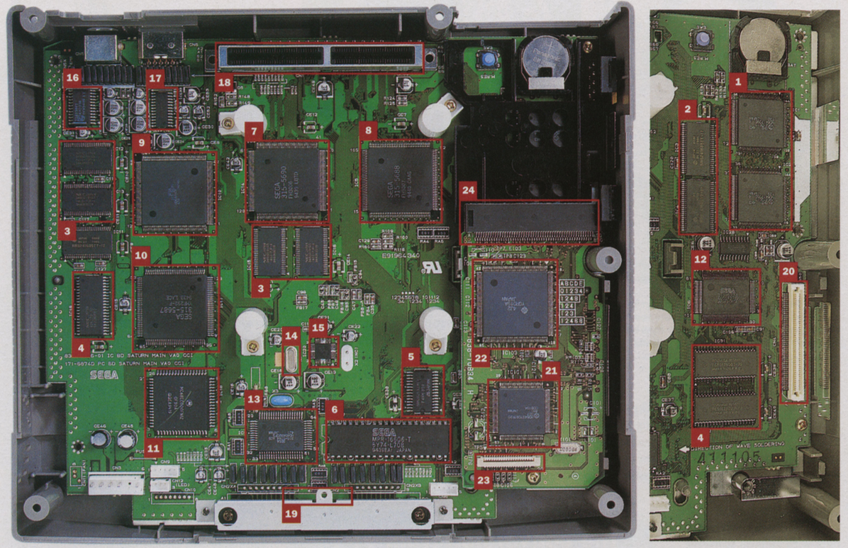
- 2x Hitachi SH·2s @28.6MHz, 25 MIPS
- 16Mbit SDRAM for SH2s
- 12Mbit SDRAM for VRAM and frame buffer
- 512K sound DRAM for 68ECOO
- 32K SRAM for battery back·up
- 512K IPL (initial program loading) ROM - initiates the Saturn’s boot-up sequence
- VDP1 32bit video display processor, sprite processor and texture-mapping engine with dual 256K frame buffers
- VDP2 32bit video display processor with five simultaneous scrolling backgrounds and two simultaneous rotation fields
- Processor controller & LSI for graphics
- Saturn Custom Sound Processor (SCSP). Contains Yamaha FH·1 DSP (11.3 MHz) and DRAM controller for sound processor
- Sound CPU - Motorola 68ECOO @22.6 MHz
- System control unit @14.3 MHz - connects the Saturn’s three buses
- System manager and peripheral control - 4bit Hitachi chip including battery back·up
- Crystal oscillator
- Integrated circuit clock controller
- Digital to analogue converter
- RGB encoder (made by Sony)
- Cartridge slot
- Connector for joypads
- Connector for CD interface
- SH·1 processor for CD drive
- MPEG interface
- CD drive board interface
- 100-pin CD drive board connector 25 Double-speed JVC CD-ROM drive with 320Kjsec data transfer rate 1
References
-
Edge (UK) issue 23 ↩